This topic describes the front and rear-panel connectors for the
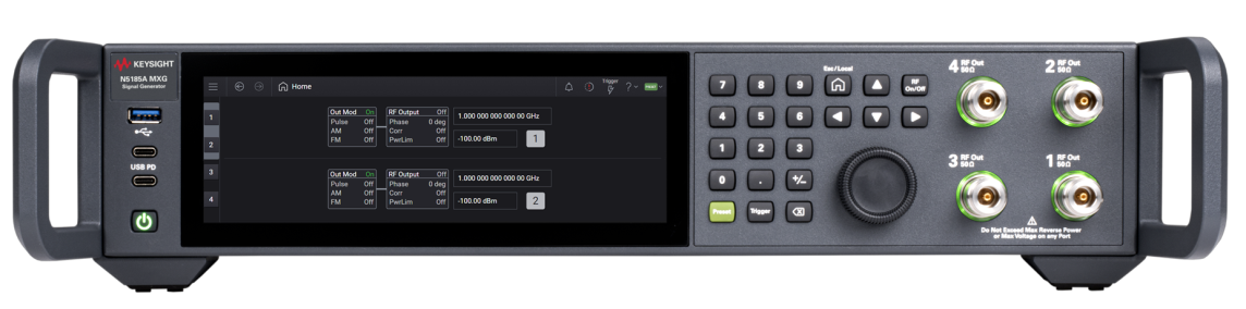
![]() View N5185A front-panel image.
View N5185A front-panel image.
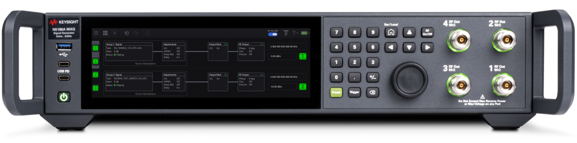
![]() View N5186A front-panel image.
View N5186A front-panel image.
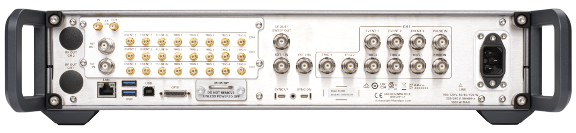
![]() View N5185A/ N5186A rear-panel image.
View N5185A/ N5186A rear-panel image.
|
Connector |
Type |
Description |
|---|---|---|
|
SS - USB 3.0 |
USB Type-A female |
Host port, SuperSpeed, 900 mA nominal (functions much like a USB port on a PC). |
|
USB PD (upper) |
USB Type-C female |
USB 3.0 Type C; "PD" indicates "power delivery"; can supply power and control inputs to external devices. |
|
USB PD (lower) |
USB Type-C female |
USB 3.0 Type C; "PD" indicates "power delivery"; can supply power and control inputs to external devices. |
|
Connector |
Type |
Description |
|---|---|---|
|
N5186A RF OUT (Ch 1 - 4) |
Type N female |
RF Output for Channels 1-4. RF Outputs for Channel 1 (Option 001), Channel 2 (Option 002), Channel 3 (Option 003) and Channel 4 (Option 004). Option 1EM moves these connectors to the rear panel. Type N female connectors; 50 Ω impedance (nominal) Max port voltage: 50 V DC Max reverse power: +33 dBm Frequency ranges: 9 kHz to 3 GHz (Option 503); 9 kHz to 6 GHz (Option 505); 9 kHz to 8 GHz Color halos around RF Out ports indicate RF output power status (Green = On, Dark = Off). Yellow indicates that RF output power is Off, but only because the RF On/Off toggle switch (or the RF Out (All) switch on the home screen) is overriding individual channel settings |
|
Connector |
Type |
Description |
|---|---|---|
|
RF OUT (Ch 1 - 4) |
2 Type N female or 4 SMA female |
Rear Panel RF Outputs (Option 1 EM). RF OUT ports are located on the rear panel if Option 1EM is ordered. These are as described in Front Panel, Right Side, with these exceptions. — If there are more than two channels, the connectors are Type SMA female. — There are no color halos around the ports when they are located here |
|
2.4 GHz IN |
SMA |
Reserved for future use. |
|
2.4 GHz OUT |
SMA |
Reserved for future use. |
|
REF OUT |
BNC |
Frequency reference output. REF OUT is an internally-generated frequency reference. Under Instrument Settings > Reference, you can choose to enable or disable the output, and set the output frequency to 10 MHz or 100 MHz. |
|
REF IN |
BNC |
Frequency reference input. REF IN accepts an externally-generated 10 MHz frequency reference. (With Option 1ER, any frequency in the range of 1 to 110 MHz can be used.). |
|
EVENT 1 & EVENT 2 (CH2 - 4) |
SMB female |
Event 1 & Event 2 output ports for Channel 2/3/4. The output-only EVENT ports for channels 2 to 4 furnish programmable timing signals generated by event n (n = 1 or 2). |
|
PULSE IN (CH 2 -4) |
SMB female |
Reserved for future use. |
|
TRIG 1 - 5 (CH 2 - 4) |
SMB female |
Trigger 1-5 input/output ports for Channel 2/3/4. The input/output TRIG ports for channels 2 to 4 can accept or generate programmable timing signals generated by trigger n (n= 1 to 5). |
|
LAN |
RJ-45 |
Local Area Network connection. GbE 10/100/1000BASE-T Ethernet: the LAN supports DHCP, connection monitoring, dynamic hostname services, TCP/IP communication, TCP keep alive, and SCPI remote programming. The LAN connector provides the same SCPI remote programming functionality as the GPIB connector, and is also used to access the internal Web server and FTP server. |
|
USB (2 ports) |
USB 3.0 Type A female |
Host ports, SuperSpeed, 900 mA nominal (these function much like a USB port on a PC). |
|
USB (1 port) |
USB 2.0 Type B female |
Device port; provides remote programming functions via SCPI (USBTMC-USB488). |
|
GPIB |
Micro-D-25-pin |
GPIB connector for SCPI-based remote control. This micro-GPIB connector provides remote programming functionality via SCPI (IEEE-488.2, 1987 with listen and talk). For GPIB cabling, use accessory Y1260A. |
|
MEMORY |
Removable tray. |
Holder for solid state drive (256 GB NVMe). |
|
LF OUT / SWEEP OUT |
BNC |
Dual-purpose output. LF OUT: a low-frequency (0 to 10 MHz) function generator. SWEEP OUT: Generates an output voltage ramp (0 to +10 V) when the signal generator is sweeping. |
|
EXT 1 IN, EXT 2 IN |
BNC |
External Inputs 1 and 2 to apply external (amplitude/frequency/phase) modulation or control signals to the signal generator. Selectable input impedance: 50 Ω, 600 Ω, or 1 M Ω See Output Modulation > AM Source or FM Source or PM Source to know more. |
|
SYNC UP, SYNC DN |
|
Reserved for future use. |
|
CH1 EVENT 1 - 3, PULSE IN |
BNC |
Event 1-3 ports for Channel 1. The output-only EVENT ports for channel 1 furnish programmable timing signals generated by event n (n = 1 to 3). The PULSE IN port is reserved for future use. |
|
CH1 TRIG 1 - 5 |
BNC |
The input/output TRIG ports for channel 1 can accept or generate programmable timing signals generated by trigger n (n= 1 to 5). |
|
STrig In |
BNC |
STrig In is used in conjunction with Global Trigger. When Global Trigger Source is set to EXTernal, the STrig In connector is used to supply the trigger. Few older N5186A instruments may have this connector labeled as Trig 6.
|
|
LINE |
3-prong plug |
AC power receptacle; accepts 3-pronged AC power cord supplied with the instrument. |